Grow · restart drip irrigation ornamental beds
Restart Drip Irrigation in Ornamental Beds Before Spring Growth Hides It
Open, flush, inspect, and retune a dormant drip system while emitters and plant root zones are still easy to see.
Published Last updated
In this guide
- Use the biological cue for drip irrigation system serving ornamental beds
- Separate hardware flow from useful soil wetting
- Read the site and the whole plant together
- Set a visible finish line before beginning
- Prepare the work while every part is still identifiable
- Carry out the central operation in a controlled sequence
- Protect roots, crowns, and new growth after the work
- Diagnose a weak response before adding another treatment
- Leave a record for the next seasonal decision
- Steps
Use the biological cue for drip irrigation system serving ornamental beds
Restart the system while dormant stems still expose the tubing and several mild hours remain for repair. Colorado State's spring sequence is specific: open the line, flush accumulated dirt, clean the filter, cap and pressurize the system, then confirm emitter operation. A controller that advances normally proves only that a valve received a command; the bed must be inspected under flow before irrigation is dependable.
Wait until local freeze risk and the system's winterization method allow water back into the assembly. A line that still needs draining, a cracked housing, or a backflow device awaiting seasonal service stays isolated. Spring rain may make plant irrigation unnecessary while the hardware is being tested, so use the shortest cycle that reveals flow, leaks, and wetting without saturating the bed.
A commissioned zone has a clean filter, clear flush discharge, dry connections, measurable output at representative emitters, and water entering current root zones. Pavement spray, an emitter beside a removed shrub, or a wet spot at the controller does not count as useful delivery. The correct finish is hydraulic and botanical: water reaches roots at the rate the parts specify, then stops cleanly.
Keep scheduling separate from repair. Extra minutes cannot open a plugged emitter, correct excessive pressure, or make a point source reach roots that have expanded beyond it. Longer operation gives every functioning outlet more water and may drown plants near the head while the far end stays dry. Establish uniform operation and placement first; derive runtime from measured output, soil movement, weather, and plant demand afterward.
Separate hardware flow from useful soil wetting
On a suitable frost-safe test day, inspect and flush one zone before trusting the controller. Measure output, then check whether water actually reaches the intended root zones. A flowing emitter can still miss a root ball, while a wet bed may need no run at all. Program from those separate observations and retain them with the zone map.
Read the site and the whole plant together
Trace water from the point of connection through the backflow device, valve, filter, pressure regulator, mainline, laterals, emitters, and flush ends. Match that sequence to the existing plan before opening a valve. Flag cracked housings, loose caps, rodent cuts, kinked polyethylene, displaced stakes, buried outlets, and tubing caught around enlarging trunks or perennial crowns.
Update the plant map at the same time. Cross out removed plants, mark new divisions and shrubs, and draw the present canopy edge of trees and woody shrubs. University of Arizona guidance places delivery farther from trunks as plants grow and calls for more or higher-flow emitters when the root system expands. A perfectly flowing emitter at last year's stem position can now serve only a small fraction of the active roots.
Read slope, soil texture, rain shadows, and access by zone. A far lateral climbing a grade can lose dynamic pressure; clay can pond beneath a high-output point; plants under eaves may remain dry after surrounding beds receive rain. Flag emerging crowns before lifting mulch and use a stable path or board on soft soil. The startup should leave roots and tubing visible enough to diagnose, not trample the bed while searching for hidden parts.
Set a visible finish line before beginning
Write one finish line for each zone: filter cleaned, ends flushed clear, fittings dry under pressure, representative outlet rates recorded, emitters assigned to current plants, and a conservative initial schedule entered from soil and weather. Leave the filter, flush ends, and sample emitters accessible. A beautifully hidden system that cannot be measured at the next visit is unfinished maintenance.
Commission a single valve at a time. Within it, choose one outlet near the head, one near the middle, and one at the far or highest end. Timed catch volumes distinguish a local clog from a zone-wide pressure problem. Soil checks beside those same points distinguish delivery from placement: equal outlet rates can still create unequal root-zone moisture when emitter position, soil, or slope differs.
Set stop conditions before opening the head assembly. The supply stays closed and pressure relieved during filter or fitting service. Hard-wired controllers, failed valves, damaged backflow protection, and changes governed by plumbing code go to a qualified professional. A cracked component, uncontrolled discharge, electrical moisture, or pressure outside the installed product's range ends the startup until the fault is isolated.
Keep the diagnostic order visible on the plan: source and valve, filtration, regulation, distribution, outlet, soil, then plant. Starting with a wilted leaf and adding runtime skips every upstream test. Starting at the head narrows the system logically and prevents a healthy section from being adjusted to compensate for one failed part.
Prepare the work while every part is still identifiable
Switch the controller off, close the supply, and relieve residual pressure before touching the filter, regulator, caps, or couplers. Assemble the manufacturer's filter-cleaning materials, compatible repair fittings, punches and plugs, catch containers, flags, and a bucket for each open end. Mixed brands can use different emitter color codes, so read the molded rate or packaging rather than relying on color alone.
Expose only the head assembly, damaged segments, representative emitters, and flush ends. Flag perennial crowns, shallow rhizomes, root flares, buried lighting, and known utilities before pins or stakes move. Route open ends into buckets. The captured grit shows whether flushing is complete and keeps sediment from washing into a crown or disappearing into mulch.
Label each valve, lateral, emitter type, and nominal gallons per hour on the plan. Arizona lists common point-source rates of 0.5, 1, 2, and 4 gallons per hour and limits quarter-inch microtubing runs to five feet. Record the actual installed product's specifications, regulator range, elevation change, and capped outlets so the timed catch test has a meaningful expectation.
Carry out the central operation in a controlled sequence
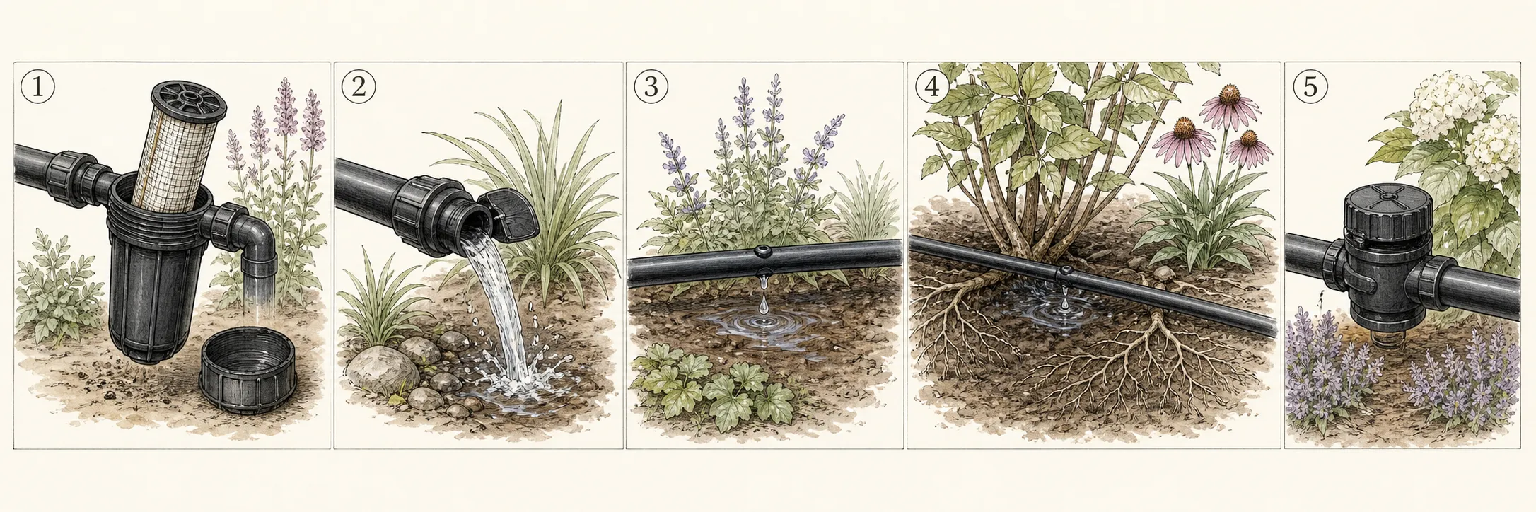
Clean the filter with the supply isolated, reinstall it in the correct orientation, and leave lateral ends open. Admit water slowly to one zone and direct discharge into buckets until grit and discoloration clear. Close the far ends, pressurize within the component rating, and inspect the head assembly and every repair. A fitting that leaks at normal pressure needs compatible replacement, not extra system pressure.
Catch the same timed interval from the mapped near, middle, and far emitters. Convert each volume to the same unit and compare it with the nominal outlet rate. One low sample points to a clogged or damaged emitter; a decline toward the far or uphill end points to pressure, elevation, line length, or excess zone flow. Uniformly high output suggests pressure or product mismatch.
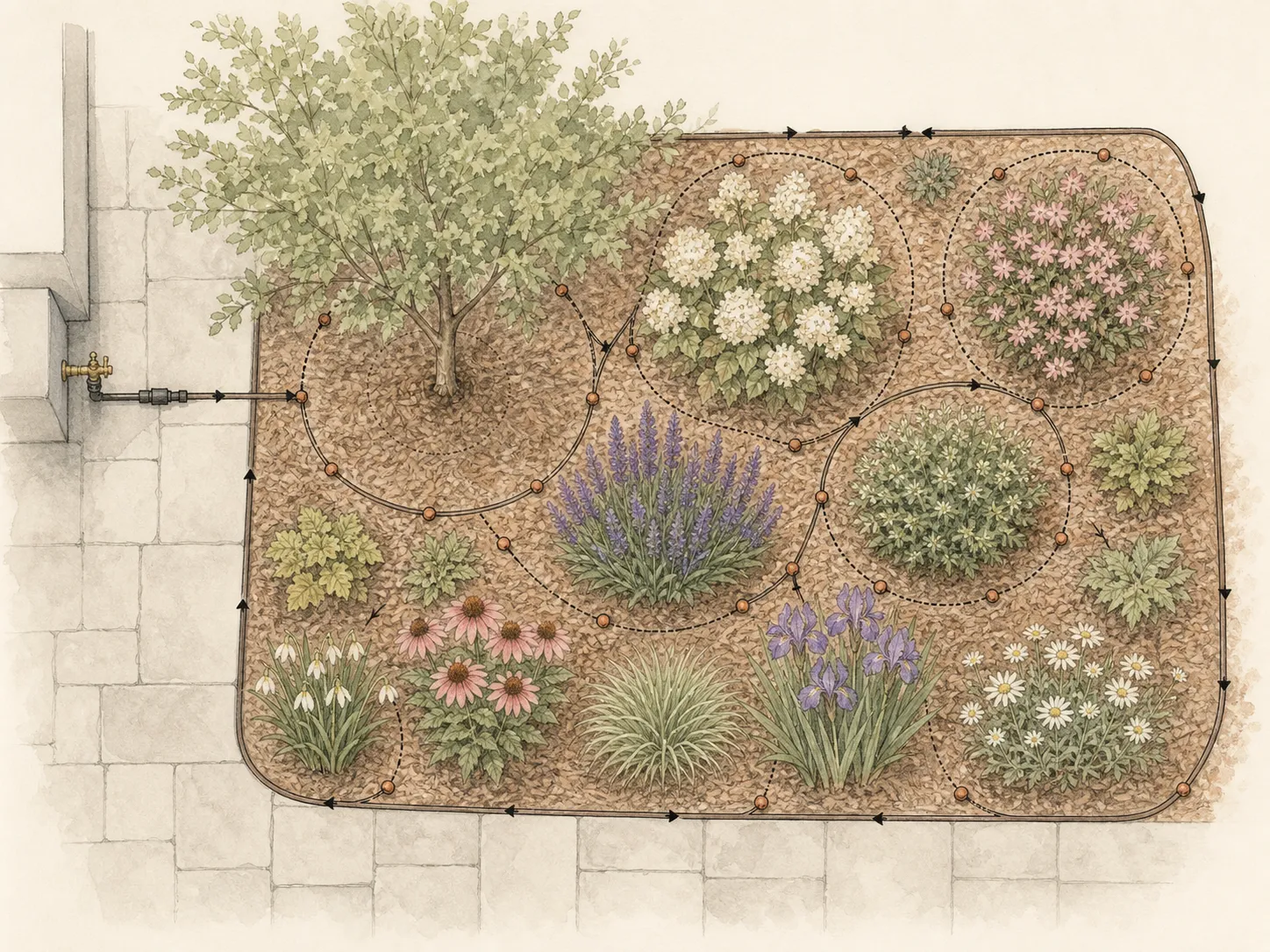
Repair hydraulic faults before moving delivery points. Then place emitters over present root zones, clear of crowns and trunks, and plug outlets serving empty gaps. Keep shrubs, trees, ground covers, and devices with substantially different application rates on appropriate zones. Sprinklers, microsprays, and point-source emitters impose different pressure and flow demands; Arizona guidance separates sprinklers from drip at the valve.
Add the nominal rates of every outlet on the valve and compare that total with available source flow and the tubing manufacturer's capacity. Colorado State illustrates the arithmetic with fifty 2-gallon-per-hour emitters: together they demand 100 gallons per hour. A zone that exceeds its supply can show acceptable output near the head and weak delivery downstream even when no emitter is clogged. Divide the zone or resize the distribution system after professional design advice if the measured supply cannot serve the mapped load.
Protect roots, crowns, and new growth after the work
Run one conservative complete cycle and inspect the wetting pattern beside the mapped outlets. Dig a narrow check at root depth after water has had time to move through the profile. RHS guidance gives useful targets for checking: about 15 centimetres for herbaceous perennials and 20 to 30 centimetres around young tree and shrub root balls. Those depths verify moisture placement; they are not fixed runtime prescriptions.
Stop the cycle when water pools, emerges downhill, reaches a crown, or leaves the intended root zone. Clay and slopes may need a lower application rate or split cycles; sand may show a narrow deep column that calls for more distribution points. A longer single run cannot repair runoff or a wetting footprint that misses lateral roots.
Use institutional emitter examples as a starting check, then verify the actual bed. Colorado State suggests two 0.5-gallon-per-hour outlets for a perennial in clay or loam where redundancy matters, and two 1-gallon-per-hour outlets about 12 inches from a newly planted small shrub or tree. Those examples assume particular plant size and soil; climate, species, establishment, and installed hardware can change the design. Their useful lesson is distribution: several measured points can wet a growing root area more reliably than one high-rate point beside the stem.
Re-cover sound tubing lightly and fasten it so pets, children, and maintenance tools are less likely to catch it. Leave the filter, flush ports, repaired couplers, and sample emitters findable. Keep mulch clear of plant crowns and trunk flares, and mark tubing crossings where edging, division, or future bulb planting could cut a live line.
Enter a conservative schedule based on measured outlet rate, root-zone depth, soil texture, slope, current rainfall, and local restrictions. Rain should cancel or delay irrigation. Recheck after leaves expand and again as temperatures rise; plant water use and emitter accessibility change even though the controller program remains unchanged.
Diagnose a weak response before adding another treatment
When one plant remains dry, catch the nearest outlet and inspect soil beside it. Correct flow with dry roots means the emitter is misplaced or the wetting volume is too small for that root system. Low flow at only that outlet means clogging or damage. Low flow from several far-end outlets sends the diagnosis upstream to filtration, pressure, elevation, line length, or total zone demand.
When one plant stays wet, compare its emitter rate, soil texture, slope position, and root condition with a healthy neighbor on the same valve. A low clay pocket may remain saturated after the valve closes, while a missing plug can create a hidden source under mulch. Reduce or relocate delivery only after confirming that the wetness belongs to irrigation and not rainfall, a leaking supply fitting, or poor drainage.
When the whole zone behaves poorly, return to the head assembly. Clean the filter, verify the correct regulator and valve operation, then repeat the near-middle-far catch test. Pressure-sensitive emitters change output along a pressure gradient; pressure-compensating models should remain steadier within their rated range. A professional should evaluate backflow faults, hard-wired controls, or pressure that cannot be reconciled with the product specification.
Leave a record for the next seasonal decision
For each valve, record filter condition, flush date, installed pressure specification, near-middle-far catch volumes, repairs, capped outlets, and observed wetting depth. Mark the sample emitters that remain unchanged as future controls. A controller screenshot belongs beside the zone map so an unexplained runtime edit can be traced to a measured decision.
Add current plant boundaries and emitter rates to the drawing. Note zones intentionally left off because rainfall supplies moisture and outlets retired after plant removal. This prevents a future startup from reopening a capped gap or treating a deliberately inactive valve as a failure. Photograph accessible flush ports and repairs before foliage hides them.
Close with one next action per zone: keep it off during wet weather, change runtime after another soil check, move or add outlets around an expanding root system, or investigate pressure and flow. Schedule a monthly visual delivery check during use and a second mapped catch test when plant growth, repairs, or symptoms suggest the original distribution has changed.
Steps
- Level
- moderate
- Time
- One focused session, followed by scheduled checks
- Tools
- Filter wrench if required, Drip punch, Flush bucket, Graduated catch containers
- Materials
- Compatible couplers and plugs, Replacement emitters, Blank tubing stakes
- 1Choose a frost-safe test day
Choose a mild interval after the local winterization requirement has ended and before regular irrigation is needed. Leave the controller off, close the supply, and compare the backflow device, valve, filter, regulator, laterals, emitters, and flush ends with the system plan. Isolate cracked parts or seasonal backflow service before admitting water.
- 2Walk and map every lateral
Trace each valve from supply to every flush end. Flag cracks, rodent cuts, kinks, buried outlets, displaced stakes, crowns, root flares, and plants whose root zones changed. Label emitter type and nominal rate from the product. Mark removed plants and new canopy edges so live outlets can be plugged, moved, or expanded intentionally.
- 3Clean the filter and open ends
With supply closed and residual pressure released, service the filter according to its design. Open the selected zone's lateral ends into buckets and stage compatible couplers, plugs, emitters, punches, and catch containers. Admit water slowly and continue flushing until grit and discoloration clear, then close the ends and inspect fittings under normal rated pressure.
- 4Flush and measure one zone
Collect equal timed samples at mapped near, middle, and far outlets and convert them to the same flow unit. Compare the results with the installed emitter rating. Repair a single low outlet locally; investigate pressure, elevation, line length, or zone demand when output declines across the run. Repeat the catch test after each hydraulic repair.
- 5Observe the wetting pattern
Place working emitters over current root zones, clear of crowns, trunks, paving, and empty gaps. Run a conservative cycle and open narrow soil checks beside the sample points. Note width and depth, pooling, and downhill movement. Change outlet placement or application rate when the wetting shape misses roots or exceeds infiltration.
- 6Program from soil and rainfall
Set each valve from measured flow, root-zone depth, soil texture, slope, plant establishment, rainfall, and local water rules. Leave wet-weather zones off. Record the controller setting with the catch and soil results, then inspect delivery monthly and retest after foliage expansion, plant removal, emitter changes, or a new dry or saturated symptom.
Sources
- Drip Irrigation for Home Gardens. Colorado State University Extension. Source record · Accessed 2026-08-30.
- The Basics of Drip Irrigation for Landscaping. University of Arizona Cooperative Extension. Source record · Accessed 2026-08-30.
- Watering. Royal Horticultural Society. Source record · Accessed 2026-08-30.